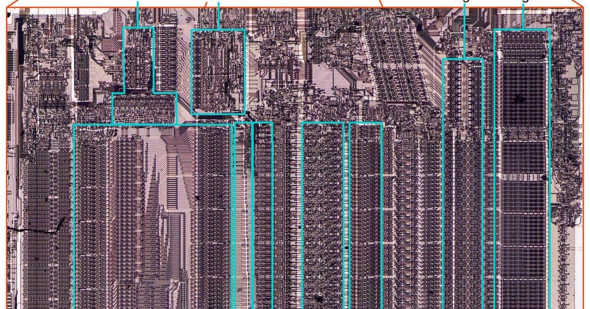
Intel 8087 floating point addition and subtraction microcode and datapath
The Intel 8087 chip sped up floating point addition by almost 100 times and used microcode, an integer adder, shifter, exponent logic, and an 80 bit temporary real format for addition and subtraction.
Why the 8087 mattered
Intel introduced the 8087 in 1980 to make floating point operations much faster in the IBM PC and other systems. The chip supported advanced operations such as tangents, square roots, and logarithms, but addition and subtraction show how the datapath worked. The 8087 sped up addition by a factor of almost 100 compared with the 8086 processor, with complicated operations improving by even more.
Inside the chip, the microcode ROM held 1648 micro instructions. The bottom half of the die was the datapath, where 80 bit values were processed. The key block was the 69 bit integer adder near the center. It received one argument from the B register and another from blocks such as the temporary registers or stack registers, then sent the result to the sum register.
Datapath blocks for basic arithmetic
Floating point addition first aligns binary points by shifting the value with the smaller exponent until the exponents match. After significands are added as integers, the result may need normalization so the significand starts with a 1 bit. If an addition produced an extra high bit, the value shifted right and the exponent increased. Subtraction could produce a positive, negative, or zero result, and normalization could require a large left shift. A negative significand was made positive and the sign flipped; a zero result returned plus or minus zero as appropriate.
The shifter moved a 68 bit value by an arbitrary number of positions left or right, and occupied much die area because shifts had to be fast. Leading zero circuitry counted zero bits or bytes on the left so they could be shifted away. An exponent converter processed exponents and detected overflow and underflow. For alignment, the CREATE_DENORM micro subroutine shifted the second argument by the exponent difference passed in the sum register.
Registers, microcode flow, and special values
Internally the 8087 used an 80 bit temporary real format with a sign bit, a 15 bit exponent biased by 16383, and a 64 bit significand. Eight registers formed a stack, and each value had a tag of zero, valid, special, or empty. Internal temporary registers included tmpA and tmpB, plus tmpC with a 68 bit significand and guard, round, and sticky bits.
Basic math operations started at microcode address 0001, moved the two arguments into tmpA and tmpB, then called a target selected by instruction type. Addition and subtraction ran from address 0232. The microcode handled zero cases, compared exponents, swapped arguments when needed, and tracked sign changes in the sign latch. It then chose unsigned addition or unsigned subtraction based on operand signs and the operation.
On the unsigned addition path, aligned significands were added, a carry triggered a one bit right shift and an exponent adjustment, precision was trimmed for 80, 64, or 32 bit values, and the exponent was checked for overflow or underflow. On unsigned subtraction, the adder computed tmpA minus tmpB, rounding bits could set a low result bit, and leading zero handling produced byte and bit shifts. The common code also handled infinities, not a number values, denormals, zeros, stack pop behavior, and interrupts for denormalized values.
Sources: righto.com
SiTech — AI-powered web development
We build fast, modern websites and bring AI into real business workflows. Have a project or a question? We'd love to help.